Ground Wire Size Chart NEC 2026: Complete Equipment Grounding Guide
Proper equipment grounding is the last line of defense against electrocution and electrical fire. The NEC specifies exact ground wire sizes based on the circuit breaker rating, and using undersized ground wire is both a code violation and a serious safety hazard. In 2026, NEC Table 250.122 remains the definitive reference for equipment grounding conductor sizing, while Table 250.66 covers grounding electrode conductors. This guide explains both tables with practical applications.
NEC Table 250.122: Equipment Grounding Conductor Sizes
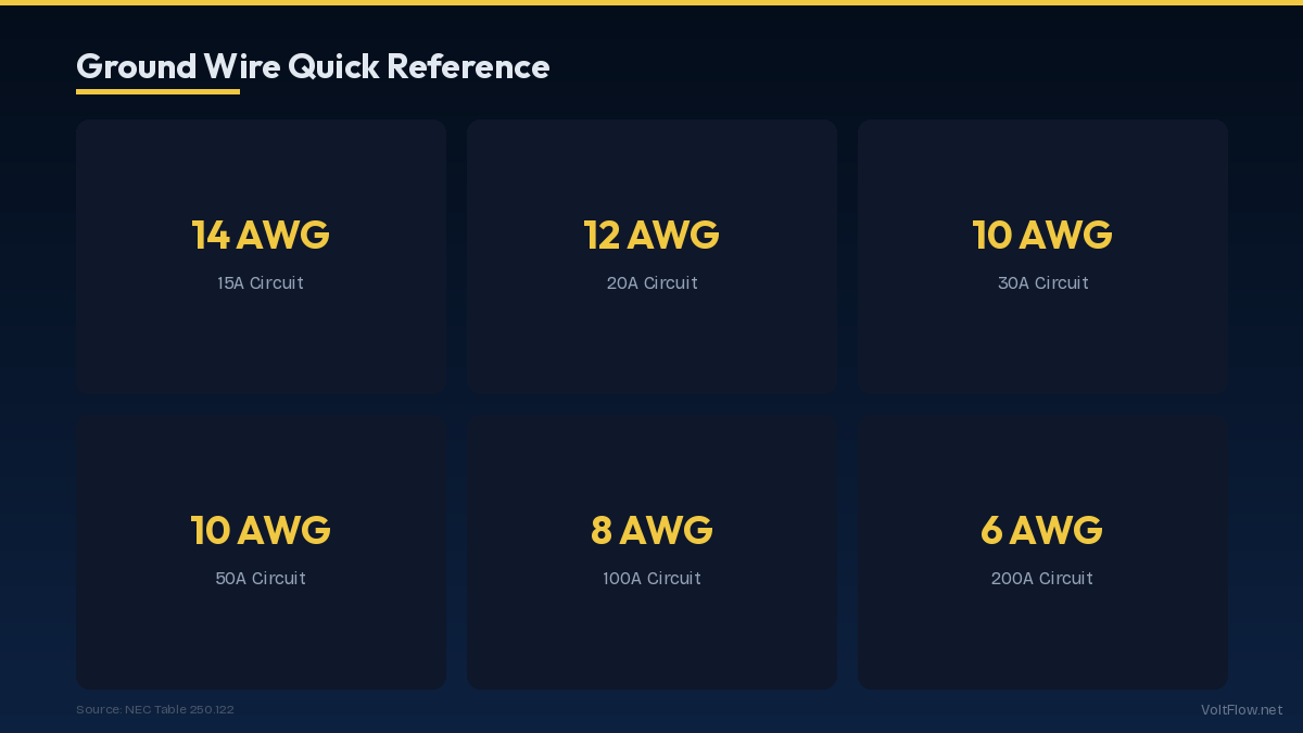
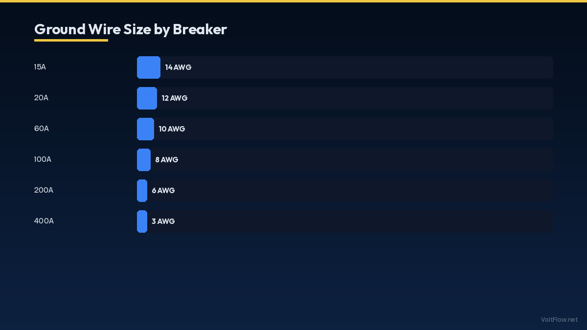
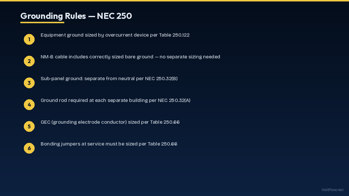
NEC Table 250.122 specifies the minimum size of equipment grounding conductors based on the rating of the overcurrent protective device, which is the circuit breaker or fuse protecting the circuit. This table applies to the green or bare ground wire that runs with the circuit conductors inside cables and conduit. For copper equipment grounding conductors, the sizes are: 15-amp breaker requires 14 AWG minimum, 20-amp breaker requires 12 AWG minimum, 30-amp breaker requires 10 AWG minimum, 40-amp breaker requires 10 AWG minimum, 50-amp breaker requires 10 AWG minimum, 60-amp breaker requires 10 AWG minimum, 100-amp breaker requires 8 AWG minimum, 200-amp breaker requires 6 AWG minimum, 300-amp breaker requires 4 AWG minimum, 400-amp breaker requires 3 AWG minimum, 500-amp breaker requires 2 AWG minimum, 600-amp breaker requires 1 AWG minimum, 800-amp breaker requires 1/0 AWG minimum, and 1000-amp breaker requires 2/0 AWG minimum. For aluminum equipment grounding conductors, each size increases by approximately two gauge numbers: 15-amp requires 12 AWG, 20-amp requires 10 AWG, 30-amp requires 8 AWG, 40-amp requires 8 AWG, 60-amp requires 8 AWG, 100-amp requires 6 AWG, and 200-amp requires 4 AWG. Notice that the ground wire does not scale linearly with breaker size. A 15-amp circuit needs 14 AWG ground while a 60-amp circuit needs only 10 AWG ground, a much smaller ratio than you might expect. This is because the ground wire only carries fault current for the brief moment between when a ground fault occurs and when the breaker trips. The wire must carry enough current to trip the breaker reliably but does not carry continuous load current. In residential NM-B cable, the ground wire is pre-sized by the manufacturer to match the cable gauge. A 14/2 NM-B cable includes a 14 AWG bare ground, 12/2 includes 12 AWG ground, 10/2 includes 10 AWG ground, and so on. When you buy the correct cable for your circuit, the ground wire is automatically the correct size. Ground wire sizing becomes a deliberate decision primarily when pulling individual conductors through conduit, where you select each wire size separately.
NEC Table 250.66: Grounding Electrode Conductor Sizes
While Table 250.122 covers the green ground wire in individual circuits, Table 250.66 covers the grounding electrode conductor, which is the wire that connects your main electrical panel to the grounding electrode system consisting of ground rods, water pipes, and building steel. This conductor provides a path for lightning energy and other high-voltage events to reach earth ground safely. The grounding electrode conductor size is based on the size of the largest service entrance conductor or equivalent area for parallel conductors. For copper grounding electrode conductors, the minimum sizes are: service entrance conductors of 2 AWG or smaller require 8 AWG GEC, service entrance conductors of 1 or 1/0 AWG require 6 AWG GEC, service entrance conductors of 2/0 or 3/0 AWG require 4 AWG GEC, and service entrance conductors of 3/0 AWG through 350 kcmil require 2 AWG GEC. For a typical residential 200-amp service using 4/0 aluminum service entrance conductors, which falls in the over 350 kcmil category for the equivalent area calculation, the grounding electrode conductor must be at least 4 AWG copper or 2 AWG aluminum. The grounding electrode conductor connects the neutral bus bar in the main panel to the grounding electrode system. In most residential installations, this consists of two ground rods driven at least 8 feet into the earth and spaced at least 6 feet apart. The conductor runs from the panel to the first ground rod and continues to the second ground rod in a continuous run without splices unless made with irreversible compression connectors. Supplemental grounding connections to a metallic water pipe within 5 feet of where it enters the building and to the building structural steel if available are also required per NEC 250.50. These supplemental connections use the same size grounding electrode conductor as the rod connections. The grounding electrode conductor must be protected from physical damage where exposed. Running it through conduit, installing protective plates where it crosses framing members, and securing it with appropriate clamps prevents accidental damage that could compromise the grounding system integrity.
Ground Wire Types and Installation Requirements
Ground wires come in several types, and the NEC specifies where each type can be used. Using the wrong type in the wrong location is a code violation even if the wire is the correct size. Bare copper wire is the most common ground conductor in residential NM-B cable and for grounding electrode conductors. Bare copper is acceptable inside walls, in conduit, and for direct-burial grounding electrode conductors. It is the standard choice for residential construction because it is the least expensive option and provides excellent conductivity and corrosion resistance in most soil conditions. Bare copper grounding electrode conductors for direct burial should be soft-drawn copper for flexibility during installation. Green insulated copper wire is required in certain applications and preferred in others. Inside conduit containing multiple circuits, the NEC requires equipment grounding conductors to be identified by green insulation or green with yellow stripe insulation per NEC 250.119. Bare ground wire is also permitted in conduit but green insulated wire provides easier identification during future maintenance. Green insulated ground wire costs slightly more than bare wire but prevents confusion during service work. Green ground screws and pigtails connect ground wires to metal outlet boxes and device grounding terminals. NEC 250.148 requires that all ground wires in a box be bonded together and to the box itself using listed grounding devices. The standard method uses a single green ground screw in a threaded hole in the metal box, with all ground wires and a pigtail wire connected under a wire nut. The pigtail connects to the ground screw. Push-in grounding connectors from Ideal and Wago simplify box grounding by providing multiple ports for ground wire connections without wire nuts. Ground wire connections must be mechanically secure and electrically reliable. Wire nuts are the most common connection method for ground wire splices. Green wire nuts specifically designed for grounding connections are available and provide visual identification. All ground wire connections should be accessible for inspection per NEC 250.8. Do not bury ground wire splices inside walls or behind permanent finishes. Grounding connections to ground rods use listed ground rod clamps, typically bronze or brass acorn-style clamps that bolt around the ground rod and secure the conductor. These clamps must be listed for direct burial and for the specific conductor and rod sizes being connected. The connection must be made on a clean section of the ground rod using proper torque to ensure a reliable long-term connection that will not loosen from thermal cycling or soil movement.
Common Grounding Mistakes and Code Violations
Grounding errors are among the most frequently cited code violations during electrical inspections, and some of these errors create genuine safety hazards that can result in electrocution or fire. Understanding the common mistakes helps you avoid them. Using undersized ground wire is the most basic grounding violation. The most frequent occurrence is using 14 AWG ground wire on a 20-amp circuit, which requires 12 AWG minimum. This happens when an electrician or homeowner uses 14/2 NM-B cable on a 20-amp breaker, which violates both the conductor ampacity (14 AWG is rated for only 15 amps) and the ground wire sizing requirements. Always match the cable gauge to the breaker rating. Missing ground connections at outlets and switches are extremely common, especially in older homes where the previous owner performed their own wiring. Every metal outlet box must be grounded. Every outlet and switch with a grounding terminal must have the ground wire connected. Missing ground connections mean that a fault in an appliance energizes the metal case without tripping the breaker, creating an electrocution hazard for anyone who touches the appliance and a grounded surface simultaneously. Bootleg grounds, where the neutral and ground are connected together at an outlet instead of running a proper ground wire, are a dangerous and all-too-common violation. This is often done to make a two-prong outlet appear to pass a three-prong outlet tester without actually running a ground wire. A bootleg ground provides no real fault protection and can energize the ground wire (and all connected metal equipment cases) during a neutral-to-ground fault condition. If you encounter an outlet that tests correctly with a plug tester but has no ground wire in the box, it is likely a bootleg ground and should be corrected immediately. Interrupted ground paths occur when a ground wire is cut, nicked, or disconnected at any point between the panel and the farthest outlet. A single interrupted ground wire leaves every downstream outlet and device without ground fault protection. During renovations, carefully maintain ground continuity through every box and connection point. Ground rods that are too short or improperly driven compromise the grounding electrode system. NEC 250.53(G) requires ground rods to be driven at least 8 feet deep. In rocky soil where a full 8-foot drive is impossible, the rod may be driven at up to a 45-degree angle or buried in a trench at least 30 inches deep. Two ground rods spaced at least 6 feet apart are required per NEC 250.53(A)(2) unless a single rod can achieve 25 ohms or less resistance to ground, which is rare in most soil conditions without testing.
Ground Wire Sizing for Special Installations
Several common residential installations have specific grounding requirements that go beyond the basic Table 250.122 sizing. Understanding these special cases ensures code compliance and safety for the specific equipment involved. Sub-panel grounding requires running a separate equipment grounding conductor from the main panel to the sub-panel, sized per Table 250.122 based on the feeder breaker rating. For a 60-amp sub-panel, the equipment grounding conductor must be at least 10 AWG copper. For a 100-amp sub-panel, at least 8 AWG copper is required. Critically, the neutral and ground buses in a sub-panel must be separated, not bonded together as they are in the main panel. The neutral bus floats and the ground bus is bonded to the sub-panel enclosure. Using 4-wire feeder cable (two hots, neutral, and ground) ensures proper separation. Using 3-wire cable without a separate ground is a code violation for new sub-panel installations. Solar panel system grounding involves both equipment grounding of the panels, racking, and inverter, plus a grounding electrode conductor for the system. NEC 690.43 requires equipment grounding conductors for DC circuits to be sized per Table 250.122 based on the overcurrent protection rating. The racking system must be bonded to the equipment ground using listed grounding lugs and bonding washers specifically designed for solar applications. Solar-specific grounding products from manufacturers like Wiley Electronics (WEEB) provide code-compliant bonding between panel frames and racking at each panel location. EV charger grounding follows standard Table 250.122 sizing. A 50-amp EV charger circuit requires a 10 AWG copper equipment grounding conductor. For hardwired EV chargers, the grounding conductor terminates at the charger grounding terminal. For plug-in chargers using a NEMA 14-50 outlet, the outlet ground pin connects through the cable to the charger internal ground. The 14-50 outlet installation must include a properly connected ground wire to the outlet ground terminal and bonded to the metal outlet box. Swimming pool equipment grounding is governed by NEC Article 680, which imposes more stringent grounding and bonding requirements than standard circuits. All pool equipment including pumps, heaters, lighting, and automation controllers must be grounded with equipment grounding conductors sized per Table 250.122. Additionally, NEC 680.26 requires an equipotential bonding grid connecting all metal pool components, the pool shell reinforcing steel, perimeter surfaces within 3 feet of the pool edge, and underwater lighting niches. This bonding grid uses 8 AWG solid copper wire and connects all components to prevent voltage differences between touchable surfaces that could cause electric shock. Pool bonding is one of the most complex residential grounding requirements and should always be performed by an electrician experienced specifically with pool installations.
Testing and Verifying Your Grounding System
A properly sized and installed grounding system must be verified to ensure it actually provides the fault protection intended. Several testing methods range from simple DIY checks to professional measurements that confirm code compliance. A three-light outlet tester is the simplest verification tool, available for $5-$10 at any hardware store. Plug it into each outlet and the light pattern indicates correct wiring, open ground, open neutral, reversed hot/neutral, and other common wiring errors. While not a complete test, it catches the most common grounding errors including missing ground connections, reversed polarity, and open neutrals. Test every outlet after any electrical work and periodically as part of home maintenance. A GFCI outlet tester with a trip button provides a more meaningful test. When you press the test button, it creates a small ground fault that should trip either the GFCI outlet or the GFCI breaker protecting the circuit within milliseconds. If the GFCI does not trip, the grounding system is either missing, interrupted, or has excessive impedance. This test verifies not just the presence of a ground wire but also its ability to carry enough fault current to activate the protective device. A multimeter set to measure resistance (ohms) between the ground pin of an outlet and the neutral pin should read less than 1 ohm. Higher readings indicate a loose connection, undersized wire, or long wire run with excessive resistance. A reading of infinity indicates a completely open (disconnected) ground. Compare the ground-to-neutral resistance at the farthest outlet on a circuit with the closest outlet to identify gradual increases that suggest deteriorating connections along the circuit. Ground rod resistance testing requires specialized equipment. A fall-of-potential tester or ground resistance clamp meter measures the resistance between your grounding electrode system and earth. NEC 250.53(A)(2) requires 25 ohms or less for a single ground rod. If the resistance exceeds 25 ohms, a supplemental ground rod must be installed. Most residential systems with two properly installed ground rods in average soil achieve 10-25 ohms. Sandy or rocky soil can produce higher readings requiring additional ground rods or a ground ring around the building foundation. Professional ground resistance testing costs $100-$200 and is recommended during new construction, after ground rod installation, and whenever grounding system integrity is questioned. An electrician performing a panel upgrade or service replacement should include ground resistance testing as part of the job to verify that the grounding electrode system meets code requirements. Document the test results for your records and for any future inspections or insurance inquiries. Keep the test results with your other home electrical documentation including the panel schedule, load calculation, and permit records.