How to Wire a 240V Outlet 2026: Step-by-Step NEC Guide
A 240-volt outlet provides the high-power connection needed for electric dryers, ranges, EV chargers, welders, and other heavy-duty equipment. Wiring a 240V outlet involves a double-pole breaker, properly sized 4-conductor cable, and the correct NEMA outlet type for your specific appliance. While this guide provides complete technical knowledge, the NEC and most jurisdictions require a licensed electrician and permit for new 240V circuit installations.
Understanding 240-Volt Circuits: How They Work
A 240-volt circuit works differently from the standard 120-volt outlets throughout your home, and understanding the underlying electrical theory helps you wire safely and troubleshoot effectively. Your home receives power from the utility through two 120-volt legs, called Line 1 (L1) and Line 2 (L2), plus a neutral conductor. Each leg provides 120 volts measured from the hot conductor to the neutral. The two legs are 180 degrees out of phase with each other, meaning when L1 is at positive 120 volts, L2 is at negative 120 volts. Measuring between L1 and L2 gives you 240 volts because the two 120-volt potentials add together due to their phase relationship. Standard 120-volt outlets use one hot leg (either L1 or L2), one neutral, and one ground. The current flows from the hot through the appliance, returns through the neutral, and the ground serves as a safety path for fault current. The neutral carries the full circuit current during normal operation. A 240-volt outlet uses both hot legs (L1 and L2), one neutral, and one ground. For pure 240-volt loads like baseboard heaters, well pumps, and some air conditioners, the current flows from L1 through the appliance and returns through L2. No current flows through the neutral during balanced 240-volt operation because the two legs handle the return current for each other. However, many 240-volt appliances also need 120 volts for controls, timers, clocks, and lights. An electric range uses 240 volts for the oven heating element and burner elements but 120 volts for the oven light, clock, and convenience outlet. The neutral conductor provides the return path for these 120-volt loads, which is why 240-volt circuits to ranges and dryers use four-conductor cable with two hots, one neutral, and one ground. The ground wire in a 240-volt circuit serves the same purpose as in any circuit: it provides a low-resistance path for fault current to trip the breaker quickly if a hot conductor contacts the metal enclosure of the outlet or appliance. The NEC requires a separate ground wire on all new 240-volt installations. Older three-wire installations that used the neutral as the ground path are grandfathered but cannot be installed new.
NEMA Outlet Types for 240V Applications
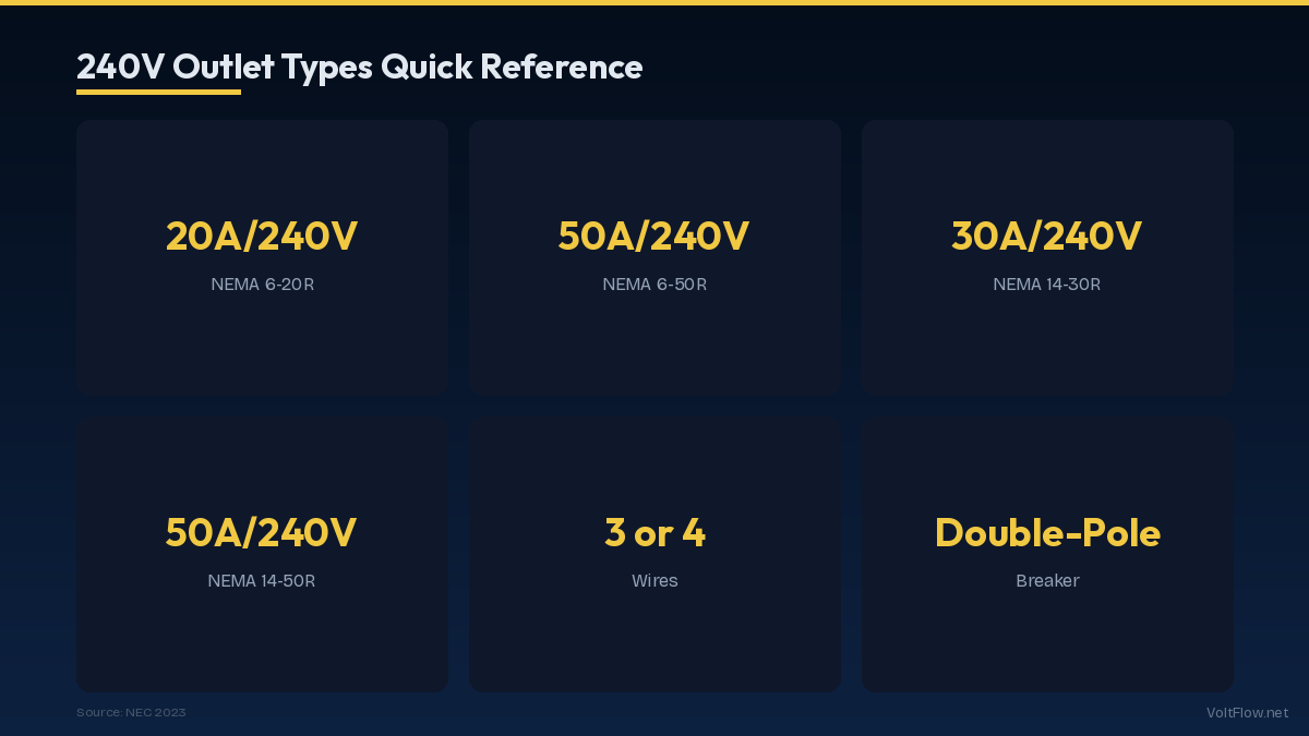
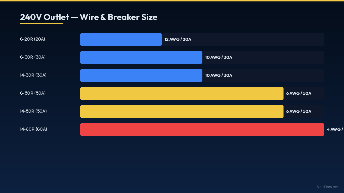
The NEMA numbering system identifies each outlet type by its voltage class, amperage rating, and pin configuration. Using the correct outlet type ensures proper connection and prevents dangerous mismatches between appliances and circuits. The NEMA 14-50R is the most versatile 240-volt outlet in residential use. It provides 50 amps at 125/250 volts with four connections: two hot, one neutral, and one ground. This outlet serves electric ranges, EV chargers, welders, and RV hookups. It uses a 50-amp double-pole breaker with 6 AWG copper wire. The physical configuration has two angled hot prongs, one straight neutral prong, and one U-shaped ground prong. This is the outlet to install if you want maximum flexibility for current and future 240-volt needs. The NEMA 14-30R provides 30 amps at 125/250 volts for electric dryers. It has four connections: two hot, one neutral, and one ground. It uses a 30-amp double-pole breaker with 10 AWG copper wire. The configuration has two angled hot prongs that differ from the 14-50 pattern, preventing interchangeability. This is the standard dryer outlet in all homes built since 1996 when the NEC required four-prong dryer outlets. The NEMA 6-50R provides 50 amps at 250 volts for dedicated 240-volt equipment like welders, plasma cutters, and some large air compressors. It has three connections: two hot and one ground. There is no neutral because these appliances use only 240 volts with no 120-volt components. It uses a 50-amp double-pole breaker with 6 AWG copper wire. The NEMA 6-30R provides 30 amps at 250 volts and serves the same pure 240-volt role as the 6-50 but at lower amperage. Mini-split air conditioner disconnect units and some workshop equipment use this outlet. It requires a 30-amp double-pole breaker with 10 AWG copper wire. The NEMA 6-20R provides 20 amps at 250 volts for window air conditioners rated above 15 amps, small welders, and workshop tools. It requires a 20-amp double-pole breaker with 12 AWG copper wire. The older NEMA 10-30R and 10-50R outlets have three prongs without a separate ground connection. These were standard for dryers and ranges before 1996 but are no longer permitted for new installations per NEC. If you have existing three-prong outlets, they are grandfathered for continued use. However, if you replace the outlet or modify the circuit, you must upgrade to the four-prong NEMA 14 series with a separate ground conductor.
Step-by-Step Wiring Process
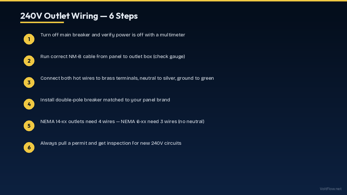
This section describes the wiring process for a NEMA 14-50R outlet on a 50-amp circuit, the most common new 240-volt installation for EV chargers and ranges. The same principles apply to other outlet types with adjusted wire sizes and breaker ratings. Step one: turn off the main breaker and verify the panel is dead using a non-contact voltage tester on the bus bars. Working on a live panel is extremely dangerous because the service entrance conductors at the top of the panel remain energized even with the main breaker off. Only the utility can de-energize these conductors by pulling the meter. Step two: install the double-pole 50-amp breaker in two adjacent panel slots. Remove the appropriate knockout in the panel enclosure for the cable entry. Feed the cable through a cable clamp or connector sized for the cable diameter. Strip approximately 12 inches of the outer jacket inside the panel, being careful not to nick the individual conductor insulation. Step three: connect the wires at the panel. The black wire connects to one pole of the breaker. The red wire connects to the other pole. The white neutral wire connects to the neutral bus bar. The bare or green ground wire connects to the ground bus bar. Tighten all terminals to the torque values specified on the breaker and bus bar labels, typically 20-25 inch-pounds for residential breakers. Under-torqued connections loosen over time and arc. Over-torqued connections damage the wire and terminal. Use a torque screwdriver for accurate and consistent tightening. Step four: route the cable from the panel to the outlet location. Use 6/3 NM-B cable for interior runs, which includes two insulated hot conductors (black and red), one insulated neutral (white), and one bare ground. Secure the cable every 4.5 feet with cable staples per NEC 334.30 and within 12 inches of each box. Step five: wire the outlet. Mount the outlet box at the desired location, typically 12-18 inches above the floor for ranges and at countertop height for other applications. Connect the black wire to the brass terminal marked HOT, the red wire to the other brass terminal marked HOT, the white wire to the silver terminal marked NEUTRAL, and the bare ground to the green terminal marked GROUND. Tighten all outlet terminals firmly. Step six: install the outlet in the box, install the cover plate, turn on the breaker, and test with a multimeter. You should measure 240 volts between the two hot slots, 120 volts between each hot and neutral, and 120 volts between each hot and ground. Any deviation from these readings indicates a wiring error that must be corrected before connecting any appliance.
Wire Selection and Cable Types for 240V Circuits
Choosing the correct wire type and gauge is critical for safety and code compliance. Different cable types serve different installation environments, and using the wrong type in the wrong location violates code and creates hazards. NM-B cable, commonly known by the brand name Romex, is the standard cable for interior residential wiring. NM-B contains individually insulated conductors plus a bare ground wire, all wrapped in a non-metallic outer jacket. For 240-volt circuits, you need NM-B with three insulated conductors plus ground, designated as 6/3 for 50-amp circuits, 8/3 for 40-amp circuits, 10/3 for 30-amp circuits, or 12/3 for 20-amp circuits. The first number is the wire gauge, and the 3 indicates three insulated conductors. NM-B is approved only for interior dry locations, inside walls, floors, and ceilings of finished or unfinished spaces. It cannot be used outdoors, in wet locations, in conduit for long runs, or embedded in concrete or masonry. UF-B cable is the underground-rated version of NM-B, suitable for direct burial at 24-inch depth or 18-inch depth under concrete. UF-B has a solid plastic jacket with the conductors embedded directly in the jacket material rather than individually wrapped. Use UF-B for circuits running underground to detached garages, sheds, or outdoor outlet locations. UF-B is more expensive than NM-B and harder to strip due to the solid jacket construction. THHN/THWN individual conductors pulled through conduit provide the most flexible installation option. Each conductor is a single insulated wire pulled through EMT, PVC, or flexible conduit. This method is required for exposed runs on exterior walls, in garages where cable would be subject to physical damage below 8 feet, and in any location where NM-B is not permitted. Individual conductors cost less per foot than cable but require more labor to install due to conduit mounting and wire pulling. For 240-volt circuits through conduit, you need four individual conductors: two hot (typically black and red), one neutral (white), and one ground (green). Conduit size must accommodate all four conductors per NEC Table C1 for EMT or Table C2 for PVC. A 3/4-inch EMT conduit handles four 6 AWG THWN conductors comfortably. A 1/2-inch conduit is adequate for four 10 AWG or 12 AWG conductors. SER cable, or Service Entrance Rated cable, is an aluminum cable commonly used for sub-panel feeders and large 240-volt circuits. SER is less expensive than copper NM-B for equivalent ampacity and is lighter and easier to route through long runs. A 4-4-4-6 SER cable provides two 4 AWG aluminum hot conductors, one 4 AWG neutral, and one 6 AWG ground, rated for 65-75 amps depending on termination temperature.
Permits, Inspections, and Safety Considerations
Installing a new 240-volt circuit requires an electrical permit in virtually every jurisdiction in the United States. This is not optional and not something that should be skipped even if you have the technical skills to do the work correctly. Permits exist to protect your safety, your home value, your insurance coverage, and future buyers of your home. The permit process begins with an application that describes the work: circuit amperage, wire type and gauge, outlet type, and purpose of the circuit. Most jurisdictions offer simple residential electrical permits for single-circuit additions, often available online for $50-$200. The permit application may require a simple diagram showing the circuit layout but typically does not need engineered drawings for standard residential circuits. After the work is complete, schedule an inspection. The inspector verifies that the breaker size matches the wire gauge, the cable is properly supported and protected, the outlet is correctly wired with proper terminal torque, the circuit has appropriate GFCI protection if required by location, and the overall installation meets NEC and local amendments. Inspections typically take 15-30 minutes for a single circuit. Common inspection failures include missing cable staples, improper cable entry into the panel without a listed connector, incorrect wire colors on terminals, missing GFCI protection in garages or outdoors, and over-filled boxes that violate NEC 314.16 box fill calculations. Insurance implications of unpermitted electrical work are severe. If an electrical fire occurs and the investigation reveals unpermitted wiring, your homeowner insurance company may deny the claim entirely. This leaves you personally liable for all fire damage, which can easily exceed the value of your home. The $50-$200 permit cost is trivial insurance against this catastrophic financial risk. Regarding DIY versus professional installation, the technical knowledge in this guide provides understanding of how 240-volt circuits work. However, actually performing the installation requires working inside an energized electrical panel. Even with the main breaker off, the service entrance conductors at the top of the panel carry full utility voltage. Contact with these conductors can cause fatal electrocution. Licensed electricians have training, insurance, and experience that protect both you and your home. For a single 240-volt circuit installation, professional electrician costs range from $300-$800 for nearby panel runs and $800-$1,500 for long or complex runs. This cost includes the permit, materials, labor, and inspection scheduling.
Troubleshooting Common 240V Outlet Problems
After installation or when diagnosing issues with existing 240-volt outlets, a systematic troubleshooting approach saves time and identifies problems safely. Always use a multimeter rather than relying on whether an appliance works, because partial failures can go undetected and cause equipment damage. Start with voltage measurements at the outlet with the breaker on and nothing plugged in. Place the multimeter leads in the two hot slots: you should read 240 volts plus or minus 5 percent, so 228-252 volts is the acceptable range. If you read 120 volts instead of 240, one leg of the breaker has tripped or one hot wire is disconnected. Double-pole breakers have independent trip mechanisms for each pole, and it is possible for one pole to trip while the other remains on. Check the breaker and reset both poles if needed. If you read 0 volts, the breaker is off or both legs are disconnected. Verify the breaker is on and firmly seated in the panel. Next, measure from each hot slot to the neutral slot: each should read 120 volts. If one reads 120 and the other reads 0, the dead leg has a broken or disconnected conductor between the panel and the outlet. Trace the wiring and check all connection points. Measure from each hot slot to the ground slot: each should read 120 volts. If these readings differ from the hot-to-neutral readings, the neutral and ground may be reversed at the outlet terminals or the ground connection is compromised. An outlet that measures correct voltage but does not power an appliance may have a poor connection that fails under load. Voltage drops significantly when current flows through a loose or corroded connection. Measure voltage at the outlet while the appliance is attempting to operate. If voltage drops below 220 volts under load, there is excessive resistance somewhere in the circuit. Common locations for poor connections include the breaker terminals in the panel, wire nut connections in junction boxes along the run, the outlet terminals themselves, and the appliance plug and cord connection. Tighten all accessible connections to proper torque specifications. If an outlet sparks when you plug in or unplug an appliance, check for damaged outlet contacts. Outlets wear out over time, especially the hot contacts that carry the most current. A worn outlet that makes intermittent contact arcs each time the plug moves slightly, generating heat that can damage the outlet and surrounding materials. Replace any outlet that sparks, feels warm to the touch, shows discoloration on the faceplate, or allows the plug to fit loosely. Replacement outlets cost $10-$20 for NEMA 14-50 and 14-30 types and take 15 minutes to swap for a competent electrician.