Cable Size Calculator UK 2026: BS 7671 Sizing Guide
Selecting the correct cable size under BS 7671 involves balancing current-carrying capacity, voltage drop, and earth fault loop impedance. The 18th Edition wiring regulations use Tables 4D1A-4D5A for copper cable ratings and Appendix 4 correction factors for installation conditions. A 7kW EV charger needs 6mm² twin-and-earth minimum on a 32A MCB. This guide covers the complete BS 7671 cable sizing method for residential UK installations.
BS 7671 Cable Sizing Method: The Three Checks
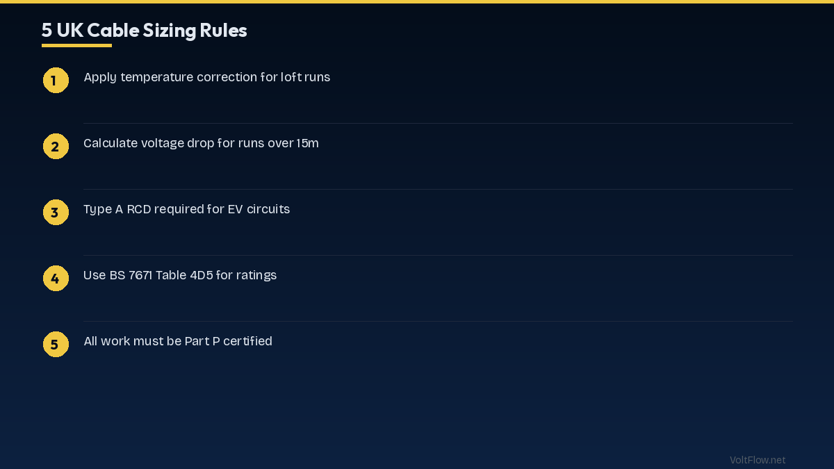
Cable sizing under BS 7671 requires passing three independent checks. The cable must satisfy all three simultaneously, and the most restrictive check determines the minimum cable size. The first check is current-carrying capacity. The cable must be able to carry the design current of the circuit without exceeding its maximum temperature rating. This is the most fundamental sizing check and uses the tabulated current ratings from BS 7671 Appendix 4, modified by correction factors for ambient temperature, grouping with other cables, and thermal insulation. The design current is the maximum sustained current the circuit will carry, calculated from the load connected to the circuit. For a 7kW single-phase EV charger, the design current is 7,000 divided by 230 equals 30.4 amps. The protective device must have a rating equal to or greater than the design current, so a 32A MCB is selected. The cable current rating after applying correction factors must be equal to or greater than the MCB rating of 32A. The second check is voltage drop. BS 7671 Regulation 525 limits the voltage drop from the origin of the installation to the point of use to 5 percent of the nominal supply voltage for lighting circuits and 5 percent for other circuits. At 230V, that is 11.5V maximum. The voltage drop is calculated using the mV/A/m values from BS 7671 Table 4D5 for flat twin-and-earth cables. For 6mm² cable, the mV/A/m value is 7.3 at operating temperature. For a 32A load on a 15-metre cable run: voltage drop equals 7.3 times 32 times 15 divided by 1,000 equals 3.5 volts, which is 1.5 percent of 230V, well within the 5 percent limit. The third check is earth fault loop impedance. The total earth fault loop impedance at the furthest point of the circuit must be low enough to ensure the protective device disconnects within the required time, which is 0.4 seconds for final circuits per BS 7671 Table 41.1. The earth fault loop impedance calculation considers the external impedance from the supply transformer to your consumer unit plus the cable impedance from the consumer unit to the load. If the total impedance is too high, a larger cable with lower resistance or a more sensitive protective device is needed. For most residential installations under 30 metres, 6mm² cable passes all three checks for 32A circuits, and 2.5mm² passes for 20A circuits. The voltage drop check becomes the controlling factor on long cable runs, while the earth fault loop impedance check becomes critical on very long runs with high external impedance.
Correction Factors: Ca, Cg, Ci, and Cc
BS 7671 correction factors modify the base current-carrying capacity of a cable to account for installation conditions that differ from the reference conditions assumed in the standard rating tables. Understanding when and how to apply these factors is essential for accurate cable sizing. Ca is the ambient temperature correction factor from BS 7671 Table 4B1. The standard cable ratings assume an ambient temperature of 30 degrees Celsius. If the cable operates in a higher ambient temperature, its current rating must be reduced. At 35 degrees ambient, Ca is 0.94 for thermoplastic cables. At 40 degrees, Ca drops to 0.87. At 50 degrees, Ca is 0.71. Cables in roofspaces where summer temperatures regularly reach 40-50 degrees must use these reduced ratings. Cables in well-ventilated rooms at normal room temperature of 20-25 degrees do not need temperature correction since the ambient is below the 30-degree reference. Cg is the grouping correction factor from BS 7671 Table 4C1. When multiple cables are bundled together or installed in the same enclosure, they heat each other and each cable must be derated. For two cables grouped together, Cg is 0.80. For three cables, Cg is 0.70. For four cables, Cg is 0.65. This factor applies when cables are clipped together on the same surface, run through the same hole in a joist, or enclosed in the same trunking. Cables that are spaced apart by at least one cable diameter do not require grouping correction. Ci is the thermal insulation correction factor from BS 7671 Table 52.2. When a cable is surrounded by thermal insulation, heat cannot dissipate normally and the cable must be derated significantly. A cable fully enclosed in thermal insulation for more than 0.5 metres uses Ci of 0.5, the cable rating is halved. A cable touching insulation on one side uses Ci of 0.75. This factor is critically important when routing cables through insulated walls and loft spaces. The combined correction factor is the product of all applicable individual factors. For a cable in a loft at 40 degrees ambient (Ca 0.87), grouped with one other cable (Cg 0.80), and touching insulation on one side (Ci 0.75): combined factor equals 0.87 times 0.80 times 0.75 equals 0.522. The minimum cable current rating must be at least the MCB rating divided by the combined correction factor. For a 32A MCB: 32 divided by 0.522 equals 61.3 amps. Looking at Table 4D5A for flat twin-and-earth cable clipped direct, 10mm² at 64A satisfies this requirement while 6mm² at 47A does not. This example shows how adverse installation conditions can push the required cable size up dramatically from 6mm² to 10mm² for the same 32A circuit.
Common UK Residential Cable Sizes and Applications
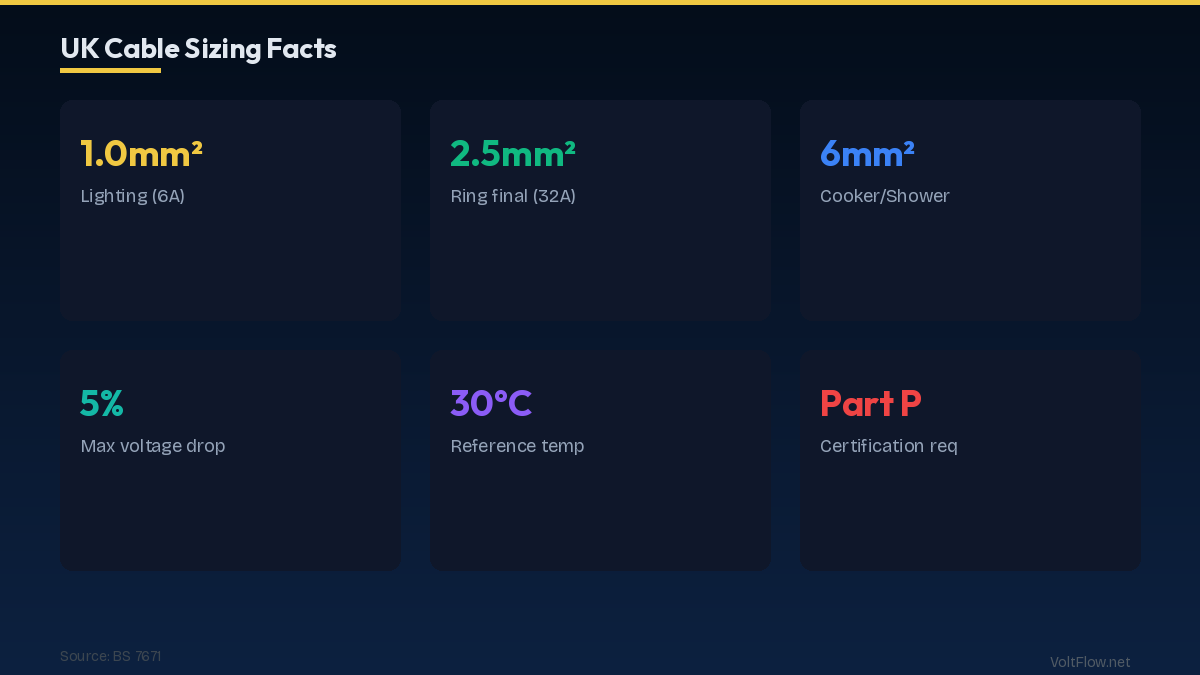
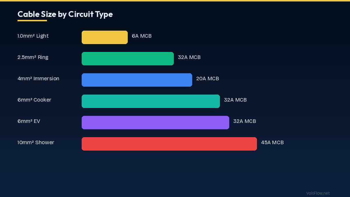
UK residential wiring uses a standardised set of cable sizes for common circuit types. These standard pairings between cable size, MCB rating, and application cover the vast majority of domestic installations. A 1mm² twin-and-earth cable is used for lighting circuits on a 6A MCB. This is the standard lighting cable for both ceiling roses and switch drops. The current rating of 15.5A when clipped to a surface provides ample capacity for a lighting circuit that rarely draws more than 5-8A. Maximum recommended cable length is 28 metres at 6A before voltage drop exceeds 5 percent. A 1.5mm² twin-and-earth cable is the alternative lighting cable used on 10A MCBs when the circuit serves a larger number of fittings or longer cable runs. Some electricians standardise on 1.5mm² for all lighting to provide additional voltage drop headroom. Current rating is 19.5A clipped direct. A 2.5mm² twin-and-earth cable is the standard ring final circuit cable serving socket outlets on a 32A MCB. The ring final circuit design means current can flow in both directions around the ring, effectively halving the current in each cable section. A 2.5mm² ring with a 70-metre maximum perimeter serves a floor area of up to 100 square metres. Spurs from the ring using the same 2.5mm² cable serve additional outlets. A 4mm² twin-and-earth cable is used for dedicated circuits to immersion heaters on a 20A or 25A MCB, and for high-power shower circuits up to 9.5kW on a 40A MCB with specific conditions. Current rating is 37A clipped direct, though the shower application requires careful voltage drop calculation on longer runs. A 6mm² twin-and-earth cable is the standard for cooker circuits on a 32A MCB serving cookers up to 13.5kW, and for EV charger circuits on a 32A MCB serving 7kW chargers. Current rating is 47A clipped direct, providing generous headroom above the 32A MCB rating. Maximum cable run for a 32A load before exceeding 5 percent voltage drop is approximately 25 metres. A 10mm² twin-and-earth cable handles electric shower circuits at 10.5-12kW on a 45A MCB and high-power cooker circuits above 13.5kW. Current rating is 64A clipped direct. This cable is noticeably stiffer and harder to route than 6mm², requiring larger bending radii and more effort to pull through joists and cavities. A 16mm² twin-and-earth cable is used for sub-main cables feeding a secondary consumer unit in an outbuilding, extension, or annex. On a 63A MCB with a current rating of 85A, it provides capacity for a full secondary distribution board serving lighting, sockets, and dedicated circuits in the remote location.
Voltage Drop Calculation: Worked Examples
Voltage drop is often the controlling factor for cable sizing on longer residential circuits, particularly for high-current loads like showers, cookers, and EV chargers installed far from the consumer unit. BS 7671 limits total voltage drop to 5 percent of 230V, which is 11.5V. Worked example one: a 7kW EV charger 20 metres from the consumer unit. Design current is 30.4A on a 32A MCB. Using 6mm² flat twin-and-earth cable with mV/A/m value of 7.3 from Table 4D5. Voltage drop equals 7.3 times 32 times 20 divided by 1,000 equals 4.67 volts. As a percentage: 4.67 divided by 230 equals 2.03 percent. This passes the 5 percent limit comfortably. If the same charger were 35 metres away: 7.3 times 32 times 35 divided by 1,000 equals 8.18 volts or 3.56 percent. Still within the limit but now consuming 71 percent of the available voltage drop budget. If other upstream voltage drop exists in the supply cable, the total might exceed 5 percent. For cable runs over 30 metres, consider upsizing to 10mm² with an mV/A/m value of 4.4, which gives only 4.93 volts drop at 35 metres. Worked example two: a 10.5kW electric shower 12 metres from the consumer unit. Design current is 45.7A on a 45A MCB. Using 10mm² cable with mV/A/m of 4.4. Voltage drop equals 4.4 times 45 times 12 divided by 1,000 equals 2.38 volts or 1.03 percent. Excellent performance. If the bathroom is 25 metres from the consumer unit through the loft: 4.4 times 45 times 25 divided by 1,000 equals 4.95 volts or 2.15 percent. Still passes but with less margin. Using 6mm² cable at this distance: 7.3 times 45 times 25 divided by 1,000 equals 8.21 volts or 3.57 percent, which passes the 5 percent test but leaves little margin for supply-side voltage drop. This is why many electricians default to 10mm² for all shower circuits regardless of distance. Worked example three: a ring final circuit serving 12 sockets over 60 metres total ring length. The maximum current in a balanced ring is half the total circuit current. At a maximum diversity of 20A per section, the voltage drop per metre of ring is halved compared to a radial circuit. Using 2.5mm² cable at 18 mV/A/m: effective mV/A/m for the ring is 9 (halved). At 20A design current over 30 metres (half the ring): 9 times 20 times 30 divided by 1,000 equals 5.4 volts or 2.35 percent. Rings inherently perform well on voltage drop because of the parallel current paths, which is one reason the ring final circuit design remains popular in the UK despite being unusual internationally.
Earth Fault Loop Impedance and Cable Selection
The third cable sizing check ensures that the earth fault loop impedance at the far end of the circuit is low enough for the protective device to disconnect within the required time during a fault. BS 7671 Table 41.1 requires disconnection within 0.4 seconds for final circuits. Each type and rating of MCB has a maximum earth fault loop impedance that must not be exceeded for guaranteed disconnection within 0.4 seconds. For a Type B 32A MCB, the maximum Zs is 1.37 ohms per BS 7671 Table 41.3. For a Type C 32A MCB, the maximum Zs is 0.69 ohms. Type B MCBs are used for most residential circuits because they allow higher earth fault loop impedance, making them suitable for longer cable runs. The total earth fault loop impedance Zs equals Ze (external impedance from the supply) plus R1+R2 (the resistance of the line and CPC conductors in the circuit cable). Ze is measured at the consumer unit and typically ranges from 0.2 to 0.8 ohms for TN-C-S (PME) supplies and 0.2 to 0.35 ohms for TN-S supplies. R1+R2 depends on the cable size and length. For 6mm² flat twin-and-earth cable, the R1+R2 per metre value is approximately 10.49 milliohms per metre at 20 degrees. At operating temperature, this increases by a factor of 1.2 to approximately 12.59 milliohms per metre. For a 20-metre run: R1+R2 equals 12.59 times 20 divided by 1,000 equals 0.252 ohms. With a Ze of 0.35 ohms: total Zs equals 0.35 plus 0.252 equals 0.602 ohms. This is within the 1.37 ohm limit for a Type B 32A MCB but would exceed the 0.69 ohm limit for a Type C 32A MCB. This is why Type B MCBs are preferred for residential final circuits. For very long runs or supplies with high Ze, upsizing the cable reduces R1+R2 and improves the earth fault loop impedance. 10mm² cable has R1+R2 of approximately 7.54 milliohms per metre at operating temperature, reducing the circuit contribution to earth fault loop impedance by approximately 40 percent compared to 6mm² cable. In installations with TT earthing (common in rural areas without PME), the earth fault loop impedance is typically much higher because the return path goes through earth rods rather than the supply neutral. TT installations almost always require RCD protection with 30mA sensitivity to achieve disconnection within 0.4 seconds, regardless of cable size. The RCD provides the required disconnection independently of the earth fault loop impedance for values up to approximately 1,667 ohms, making cable sizing for earth fault loop impedance less critical in RCD-protected TT installations. However, the cable must still pass the current-carrying capacity and voltage drop checks independently.
Special Considerations: SWA, Armoured, and External Cables
Some residential installations require cable types beyond standard flat twin-and-earth, particularly for outdoor circuits, underground runs, and detached buildings. Understanding when to use these specialist cables ensures code compliance and long-term reliability. Steel Wire Armoured or SWA cable is the standard for underground cable runs to garages, garden offices, outbuildings, and external lighting installations. SWA consists of insulated conductors surrounded by steel wire armour that provides mechanical protection against damage from digging, impact, and ground movement. The steel armour also serves as the Circuit Protective Conductor or earth path, eliminating the need for a separate earth core in many installations. SWA cable must be buried at minimum 450mm depth when under a garden or soft ground, or 600mm under a driveway or area subject to vehicular traffic. A sand bed and cable marker tape above the cable provide additional protection and identification. The cable route should be recorded on a plan kept with the installation certificate for future reference. Direct burial without conduit is acceptable for SWA cable because the armour provides the required mechanical protection. For outdoor circuits feeding a detached garage or garden office, typical SWA specifications are 6mm² 3-core SWA for a 32A supply serving lighting and sockets in the outbuilding, 10mm² 3-core SWA for a 45A supply serving additional high-power circuits like an electric heater or workshop equipment, and 16mm² 3-core SWA for a 63A supply feeding a secondary consumer unit with multiple circuits. The armoured cable terminates at each end using a cable gland that grounds the steel armour and provides a weatherproof seal. The gland connects the armour to the earthing system at both the supply and load ends. Proper gland installation and termination are critical for both safety and moisture protection. Armoured cable costs approximately 50-100 percent more per metre than equivalent flat twin-and-earth but is the only acceptable option for buried or exposed outdoor runs. The total cost for a 20-metre SWA run to a garage including cable, glands, burial, and backfill ranges from £400-£800 depending on cable size and ground conditions. Surface-mounted exterior cable on the outside of buildings should be run in UV-resistant PVC conduit or trunking to protect against sunlight degradation. Standard grey PVC conduit is suitable for short exterior runs. For longer exposed runs, black UV-stable conduit provides better long-term protection against ultraviolet degradation that can cause white or grey PVC to become brittle over 10-15 years of sun exposure.